Tyre Cutter Blade Wear: When Capacity Loss Needs Inspection




A tyre cutter rarely fails in a single, obvious moment. More often, maintenance teams notice that the machine is taking longer to process the same feed, the discharge becomes less uniform, or operators begin making repeated adjustments to keep material moving. These are capacity symptoms, but they do not automatically prove that blades are worn out. Feed condition, screen blockage, drive slip, incorrect knife clearance, and poor material presentation can produce similar results.
The maintenance task is to separate normal production variation from a blade condition that has reached the point of inspection or intervention. Waiting until cutting has visibly deteriorated can increase power demand, overload shafts and bearings, create inconsistent tyre fragments, and turn a planned blade service into an unplanned stoppage. A structured inspection routine helps identify whether the loss is caused by cutting geometry, machine condition, or upstream handling.
What capacity loss looks like in tyre cutting operations
Capacity should be judged against the machine’s own normal operating baseline, not against a nameplate figure taken in isolation. Actual throughput depends on tyre size, passenger versus truck tyre mix, bead content, feed consistency, ambient conditions, pre-processing steps, and the required output size. A line handling mostly clean, similarly sized passenger tyres will behave differently from one receiving mixed casings with mud, rims, sidewall variations, or irregularly cut feed pieces.
A capacity-related blade problem often develops as a pattern rather than one isolated observation. Operators may report longer cutting cycles, increased recirculation of oversized pieces, more frequent feed reversals, or a tendency for tyres to bounce or stall at the cutting zone. Maintenance personnel may see a corresponding rise in motor load during comparable runs, more heat around the cutting chamber, or an increase in fine rubber and wire exposure caused by tearing rather than a clean shear.
These symptoms deserve attention when they persist under broadly similar feed conditions. A short-term slowdown after a change in tyre mix is not the same as a sustained reduction in output across ordinary production runs. The useful question is not simply, “Is the machine slower?” It is, “Has the relationship between feed, energy use, cutting action, and output changed?”
Why worn blades reduce output before they appear unusable
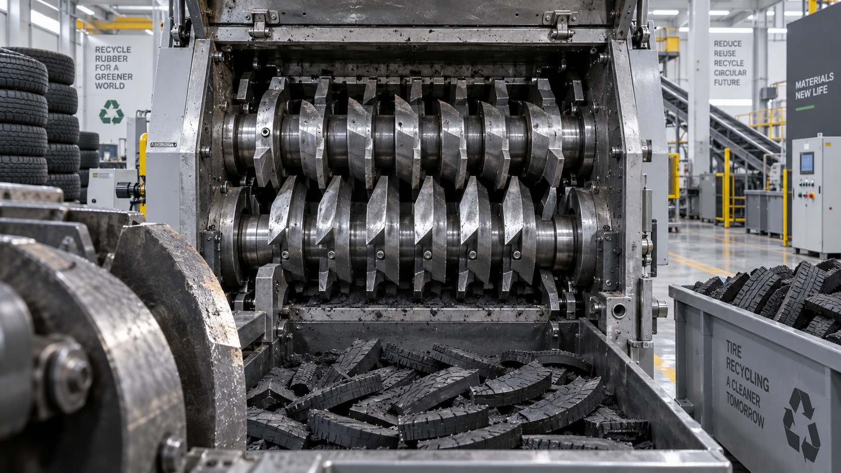
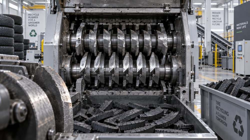
A cutter blade works by concentrating force along a controlled edge and passing close to a mating blade, counter-knife, or screen-related cutting interface. As the edge rounds, chips, or loses its intended profile, the material is increasingly compressed, dragged, and torn before separation occurs. Tyres are especially demanding because rubber can deform substantially while embedded textile reinforcement and steel wire resist the cut in different ways.
When the edge is sharp and the clearance is correct, the cutting force is concentrated over a relatively narrow zone. As wear enlarges that contact zone, the machine may require more torque to achieve the same cut. Material can remain engaged with the rotor longer, which reduces the number of productive cutting events per unit of time. This is why a machine may still run without an alarm while its usable capacity declines.
Blade wear is rarely uniform. Outer rotor positions, high-feed impact areas, and knives that repeatedly encounter bead-rich sections may deteriorate faster than others. A single damaged knife can disrupt the cutting pattern, especially where the machine relies on close, repeated intermeshing of multiple blades. Looking only at the most accessible edges can miss localised defects that are driving the problem.
Separate blade wear from other causes before opening the chamber
Opening a cutter chamber carries time, safety, and contamination costs. A brief operating review can narrow the inspection scope and prevent blade replacement from being used as a default response to every throughput complaint. The following checks are usually practical before deciding that knife wear is the primary cause.
Start with production records if they exist. Compare a recent shift with an earlier run using broadly similar tyre types and output requirements. Review motor current trends, stoppage reasons, and the amount of material rejected or recirculated. A recurring change in several indicators is more meaningful than a single operator impression.
Then inspect the material path without entering hazardous areas. Check whether feed conveyors are delivering tyres consistently, whether compression or hold-down devices are operating correctly, and whether material is bridging above the cutter. Confirm that downstream discharge equipment is not backing up into the cutting chamber. A restricted discharge can make a healthy blade set appear ineffective because cut material has no clear path out.
When a blade inspection is justified
A planned chamber inspection is usually warranted when a sustained capacity loss is accompanied by one or more cutting-quality changes: higher and less stable drive load, repeated difficulty processing similar tyre sections, a growing quantity of oversize pieces, visible tearing, or a change in noise and vibration that cannot be explained by feed conditions.
Inspection should also follow any credible foreign-object event. Rim fragments, tools, hardened metal contamination, and improperly prepared tyres can chip or fracture cutting edges. Continuing production after such an event may spread damage to adjacent knives, spacers, screens, shafts, or bearings. The priority is not to confirm a cosmetic mark; it is to determine whether the cutting geometry and structural integrity remain acceptable for safe operation.
Before access, isolate all energy sources under the site’s established lockout procedure and verify that stored mechanical, hydraulic, pneumatic, and electrical energy has been controlled. Rotors can retain movement potential, and cutter chambers contain sharp components even when stopped. Cleaning the chamber sufficiently to see the edges is part of the inspection, not a housekeeping extra.
What to examine inside the cutter
Inspect each accessible knife position systematically rather than relying on a general visual scan. Look for edge rounding, chipped corners, cracks, missing material, polished wear bands, and a blade profile that differs noticeably from comparable positions. Note whether damage is concentrated near the feed entry, bead-contact area, or one side of the rotor. A repeating pattern can point to alignment, feed presentation, or rotor support issues rather than simple end-of-life wear.
Check knife fastening components for looseness, damaged threads, fretting marks, or evidence that a blade has moved in its seat. Examine spacers and supports for wear that may alter knife position. Clearance and overlap matter as much as edge sharpness: a usable blade profile may still cut poorly if components no longer maintain the intended relationship between opposing cutting surfaces.
Where the manufacturer’s service information provides limits, use those limits for blade height, thickness, clearance, torque, and permissible regrinding. If no reliable limit is available, document the observed condition and compare like-for-like blade positions while seeking technical confirmation before altering geometry. Grinding a blade beyond its intended form, or fitting unmatched knives in a high-load rotor, may create a short-lived improvement while increasing imbalance and stress.
Blade condition is only one part of the cutting system
Many maintenance decisions become clearer when the cutter is treated as a system rather than a collection of replaceable knives. Rotor bearings influence blade engagement. Shaft deflection can change clearance under load. A worn screen changes retention time and output size. Incorrectly tensioned belts, slipping couplings, or weak hydraulic performance can limit torque delivery. Even an effective blade set cannot compensate for a feed arrangement that presents whole tyres in an unstable or uncontrolled manner.
For teams reviewing equipment configurations or replacement arrangements, a product category such as a шинорез is relevant because cutter design, blade access, screen arrangement, and intended downstream processing all affect how wear is assessed. The terminology can vary between cutter, shredder, and size-reduction machine, so maintenance documentation should identify the actual rotor and knife arrangement rather than relying only on the equipment’s general name.
Replacement decisions should consider the full set of interacting parts. Replacing only the visibly worst blades may be appropriate when damage is clearly local and the remaining knives meet the required condition. In other situations, a mixed set can produce uneven cutting loads or inconsistent particle size. The correct choice depends on the machine design, the degree of wear across positions, the availability of matched parts, and whether the cutter can be reset to the required geometry after service.
Use evidence to choose between adjustment, rotation, regrinding, and replacement
A blade does not always need replacement at the first sign of wear. Some cutter designs allow knife rotation to a fresh edge; others permit regrinding within defined limits. These options can reduce consumable use, but only when the resulting blade profile, thickness, mounting condition, and balance remain suitable. Rotating or grinding without checking clearances and matching components can conceal the underlying problem.
- Adjustment may be appropriate when edge condition remains acceptable but measured clearance, mounting security, or counter-knife position has drifted.
- Rotation may suit reversible knives with an unused edge, provided all relevant positions are handled according to the equipment design and wear pattern.
- Regrinding can be considered when permitted by the blade specification and when the process can reproduce the intended cutting angle without overheating or removing excessive material.
- Replacement is generally safer when knives are cracked, heavily chipped, distorted, below their service limit, or part of a wear pattern that cannot be corrected by setup.
After any blade work, do not judge success by sound alone. Run an appropriately controlled trial with representative material. Observe feed stability, output consistency, drive behaviour, vibration, and inspection access points for abnormal heat. The objective is to confirm that cutting quality has recovered without introducing a new mechanical issue.
Build a maintenance trigger that operators can use
Operators are often the first to detect a capacity change, but their observations need a clear route into maintenance planning. A useful trigger sheet can include tyre type, estimated feed rate, recurring stall location, oversize output, unusual noise, current draw where available, and any foreign-material event. It does not need to be complicated. Its value comes from making conditions comparable over time.
Set inspection triggers around changes from the machine’s known operating pattern, not a universal throughput number. A cutter processing mixed tyres may have wide normal variation; a line with tightly controlled feed may justify a narrower trigger. Include planned visual checks during routine shutdowns, especially after processing difficult feedstock or after a disruption that could have introduced metal contamination.
Blade wear becomes a capacity issue when it changes the cutter’s ability to produce controlled size reduction at a stable load and with predictable downtime. Inspecting at that point gives maintenance teams options: correct the setup, service the blades, address an upstream cause, or plan replacement before the machine’s output and mechanical condition deteriorate together.
Related News
- 00
0000-00
How to Evaluate a PET Bottle Recycling System Supplier for Reliable rPET Output - 00
0000-00
How to Select Rubber Processing Equipment for High-Precision Automotive Seals - 00
0000-00
How to Qualify a Servo Injection Molding Exporter for Global Sourcing - 00
0000-00
Polymer Processing for Extrusion: How Melt Rheology Affects Line Stability - 00
0000-00
Energy-Efficient Polymer Processing: Where Plants Can Cut kWh per Kilogram
Tags
Weekly Insights
Stay ahead with our curated technology reports delivered every Monday.
Related News
 Ms. Elena RodriguezGerman Extrusion Equipment Suppliers: Comparing Service, Lead Times, and Lifecycle CostExtrusion equipment Germany suppliers compared: evaluate service coverage, credible lead times, spare-parts access, and lifecycle cost to select a reliable, future-ready production partner.Sep 22, 2026
 Ms. Elena RodriguezWhat Should You Check Before Buying a Used Plastic Recycling Line?What should I check before buying a used plastic recycling line? Explore feedstock fit, wear, trials, utilities, controls, and restoration costs before you invest.Sep 26, 2026
 Ms. Elena RodriguezHow to Compare Pelletizing Lines by Energy Use per TonHow do I compare pelletizing lines by kWh per ton? Learn to measure total energy, verify saleable output, and select a cost-efficient line.Sep 23, 2026
 Ms. Elena RodriguezTyre Cutter Blade Wear: When Capacity Loss Needs Inspectionшинорез blade wear can quietly reduce tyre-cutting capacity. Learn the warning signs, inspection triggers, and maintenance actions that protect output and uptime.Sep 28, 2026
 Ms. Elena RodriguezIn-House Recycling for Factory Scrap: How to Reduce Material Waste and Disposal CostsIn house recycling for factory scrap helps manufacturers cut material waste, reduce disposal costs, and create controlled, quality-focused reuse loops.Sep 07, 2026
 Ms. Elena RodriguezHow Recyclable Packaging Manufacturing Balances Material Recovery and Production CostRecyclable packaging manufacturing: discover how smarter design, feedstock control, and process optimization reduce recovery costs while improving quality and yield.Sep 04, 2026
 Ms. Elena RodriguezHow to Evaluate a Plastic Recycling Systems Supplier for Your Processing NeedsChoose the right plastic recycling systems supplier with a practical guide to feedstock fit, output quality, total cost, testing, service, and compliance.Sep 01, 2026
 Ms. Elena RodriguezCE Marking for Plastic Processing Equipment: Documentation and Safety ChecksPlastic processing equipment CE compliance: learn the essential documentation, risk assessments, safety checks, and validation steps for reliable EU market access.Aug 30, 2026
 Ms. Elena RodriguezPlastic Packaging Compliance Standards: What Tests and Documents Matter Most?Plastic packaging compliance standards explained: learn which migration tests, mechanical checks, and audit-ready documents matter most to reduce risk and pass reviews with confidence.Aug 25, 2026
 Ms. Elena RodriguezHow to Evaluate a Plastic Waste Recycling System for Capacity, Contamination, and ROIPlastic waste recycling system evaluation made practical: compare true capacity, contamination control, and ROI to choose a line that delivers stable output and stronger returns.Aug 24, 2026
 Ms. Elena RodriguezPackaging Molding Equipment Price: What Drives Cost and How to Compare Quotes?Packaging molding equipment price varies by machine type, automation, tooling, energy use, and service scope. Learn what drives cost and how to compare quotes with confidence.Aug 21, 2026
 Ms. Elena RodriguezWhat Packaging Machinery for Plastic Containers Should You Choose for High-Volume Production?Packaging machinery for plastics containers can make or break high-volume production. Learn how to choose the right line for speed, consistency, compliance, and lower lifecycle costs.Aug 16, 2026
 Ms. Elena RodriguezWhat Circular Plastics Mean for Automotive Parts and Material SelectionCircular plastics for automotive are reshaping part selection with lower weight, better sustainability, and reliable performance. Discover how engineers balance recycled content, durability, and compliance.Aug 15, 2026
 Ms. Elena RodriguezBroiler Farming in Cage System: Selection Factors for Commercial FarmsBroiler farming in cage system selection for commercial farms: compare structure, ventilation, automation, and manure handling to improve efficiency and avoid costly mistakes.Aug 14, 2026
 Ms. Elena RodriguezHow to Implement Smart Polymer Manufacturing Without Disrupting Existing Production?Smart polymer manufacturing implementation made practical: learn how to upgrade existing production with phased digitalization, less downtime, better control, and measurable ROI.Aug 11, 2026
 Ms. Elena RodriguezHow to Evaluate a Rubber Compression Molding Supplier for Complex Part ProductionRubber compression molding supplier selection for complex parts starts with process, material, and tooling control. Learn how to compare vendors beyond price and reduce launch risk.Aug 10, 2026
 Ms. Elena RodriguezPackaging Compliance in Canada: Key Labeling and EPR Rules Importers Must KnowPackaging compliance Canada explained for importers: learn bilingual labeling, environmental claims, and provincial EPR rules to reduce risk, avoid costly errors, and stay market-ready.Aug 03, 2026
 Ms. Elena RodriguezWhy Circular Plastics Economy Traceability Matters for Recycled Content ComplianceCircular plastics economy traceability is essential for proving recycled content compliance across sourcing, processing, and reporting. Learn how strong evidence reduces audit risk.Aug 02, 2026
 Ms. Elena RodriguezRecycled Plastic Compliance: Key Standards, Testing Requirements, and DocumentationRecycled plastic compliance explained: key standards, testing requirements, supplier documents, and food-contact risks to help you avoid approval delays and costly compliance mistakes.Aug 01, 2026
 Ms. Elena RodriguezHow to Evaluate an Extrusion Machinery Manufacturer for Quality, Support, and ROIExtrusion machinery manufacturer selection affects quality, uptime, and ROI. Learn how to compare process fit, output claims, service, compliance, and long-term operating costs.Jul 29, 2026