CE Marking for Plastic Processing Equipment: Documentation and Safety Checks




CE marking for plastic processing equipment requires evidence that the machine has been designed, built, documented, and supplied in a form that meets the applicable European Union requirements. The mark placed on an injection molding press, twin-screw extruder, blow molding line, rubber vulcanizing press, shredder, or pelletizing system is the visible result of a wider conformity assessment process. A machine can appear mechanically robust and still present a compliance problem if its safety functions are undocumented, its manuals do not match the delivered configuration, or its declared limits fail to reflect actual processing conditions.
For plastic processing equipment CE compliance, the technical file and the physical machine must describe the same product. This alignment becomes difficult when a standard base machine is supplied with optional automation, larger dies, downstream haul-off units, robot interfaces, material feeding systems, recycling modules, or customer-specific guarding. Each addition can alter hazards, performance limits, electrical interfaces, and emergency-stop coverage. Documentation assembled before final configuration often becomes unreliable unless changes are formally controlled.
Define the equipment boundary before assessing conformity
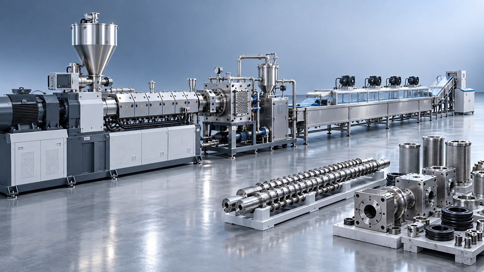
The first practical question is whether the supplied item is a complete machine, partly completed machinery, or an assembly of machinery. A standalone molding press may be supplied ready for production, while an extrusion line can include gravimetric dosing, vacuum conveying, an extruder, screen changer, melt pump, die, cooling tank, haul-off, cutter, winder, and control system. The conformity boundary must be explicit because safety responsibilities at an interface can otherwise be omitted.
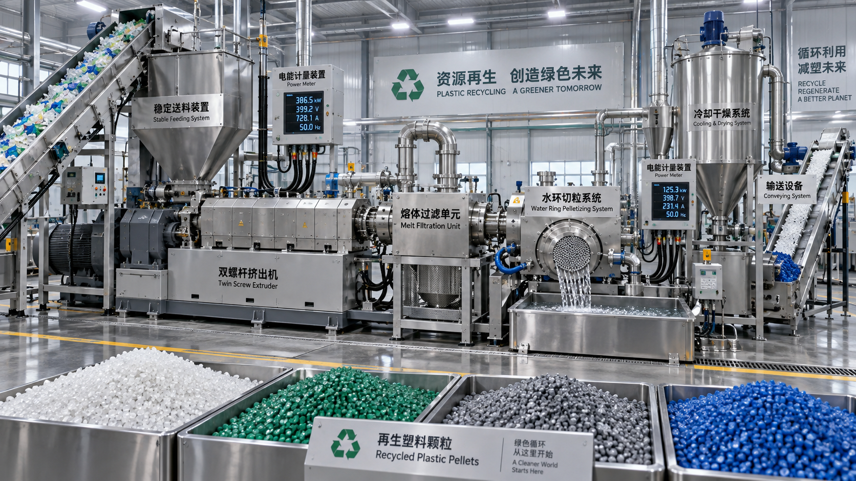
For example, the emergency-stop circuit of a pelletizing line may stop the extruder drive but leave an upstream shredder rotating or allow a downstream conveyor to continue carrying hot pellets. A guard switch on a die-face cutter may remove torque from the cutter motor but not isolate melt pressure in the extruder barrel. These are not merely wiring details. They affect the risk assessment, electrical diagrams, operating instructions, and declaration covering the assembled system.
Where multiple machines are integrated, records should identify the party controlling the final safety logic, line start sequence, restart prevention, access guarding, and handover conditions. A supplier declaration for each individual machine does not automatically demonstrate conformity of the complete installation. The technical file should show the intended arrangement, interfaces, safety-related signals, and conditions that must be satisfied during installation.
Risk assessment must follow the real process
A useful risk assessment begins with the machinery lifecycle: transport, unloading, assembly, commissioning, normal production, cleaning, tool changes, fault recovery, maintenance, decommissioning, and disposal. Plastic processing lines involve hazards that change with temperature, material state, pressure, motion, and contamination. A generic matrix copied from another machine may overlook the moments when exposure is greatest.
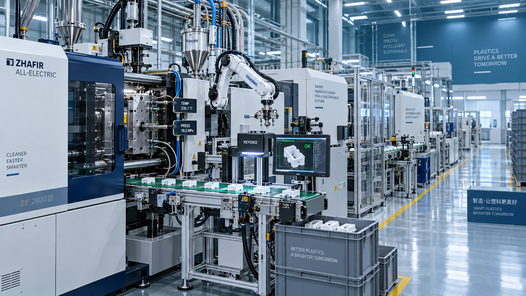
Injection molding equipment requires attention to mold-closing force, nozzle contact, plasticizing screw rotation, hydraulic or electric axis movement, hot barrel surfaces, and residual pressure before nozzle or mold work. On all-electric machines, the absence of hydraulic oil does not remove stored-energy hazards. Moving platens, ball screws, servo axes, and heated components remain capable of causing serious injury.
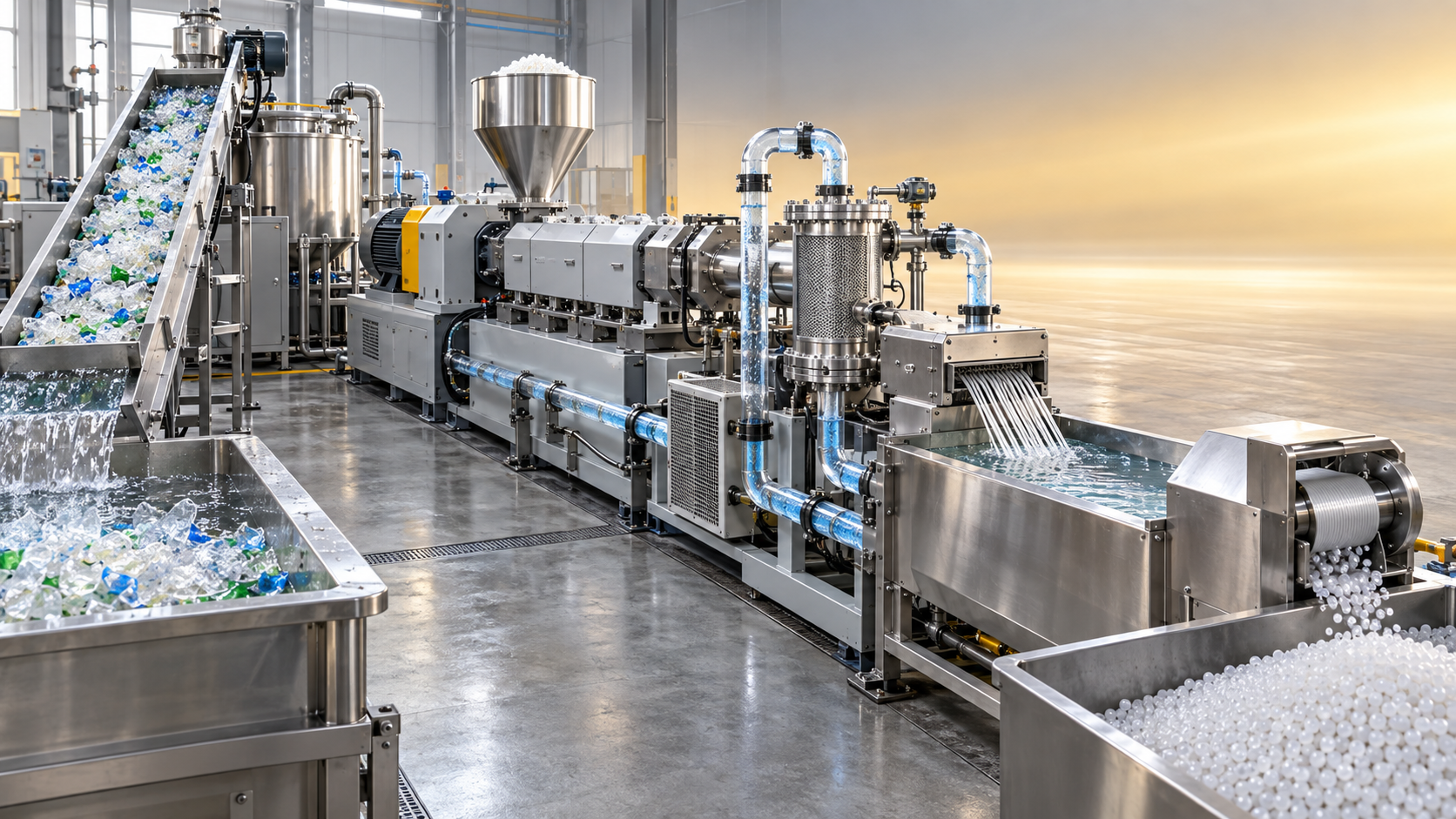
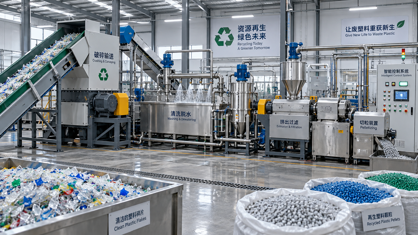
Extrusion and recycling equipment create a different pattern. Feed openings may expose rotating screws or cutters; material bridges can tempt manual intervention; degassing sections can release fumes; and blocked dies or screen packs can retain dangerous melt pressure. In a recycling line, input variability matters. Films, rigid flakes, labels, moisture, metal fragments, and residual contaminants can change torque, temperature, emissions, and blockage behavior. Safety assumptions based only on clean virgin resin may not represent intended use.
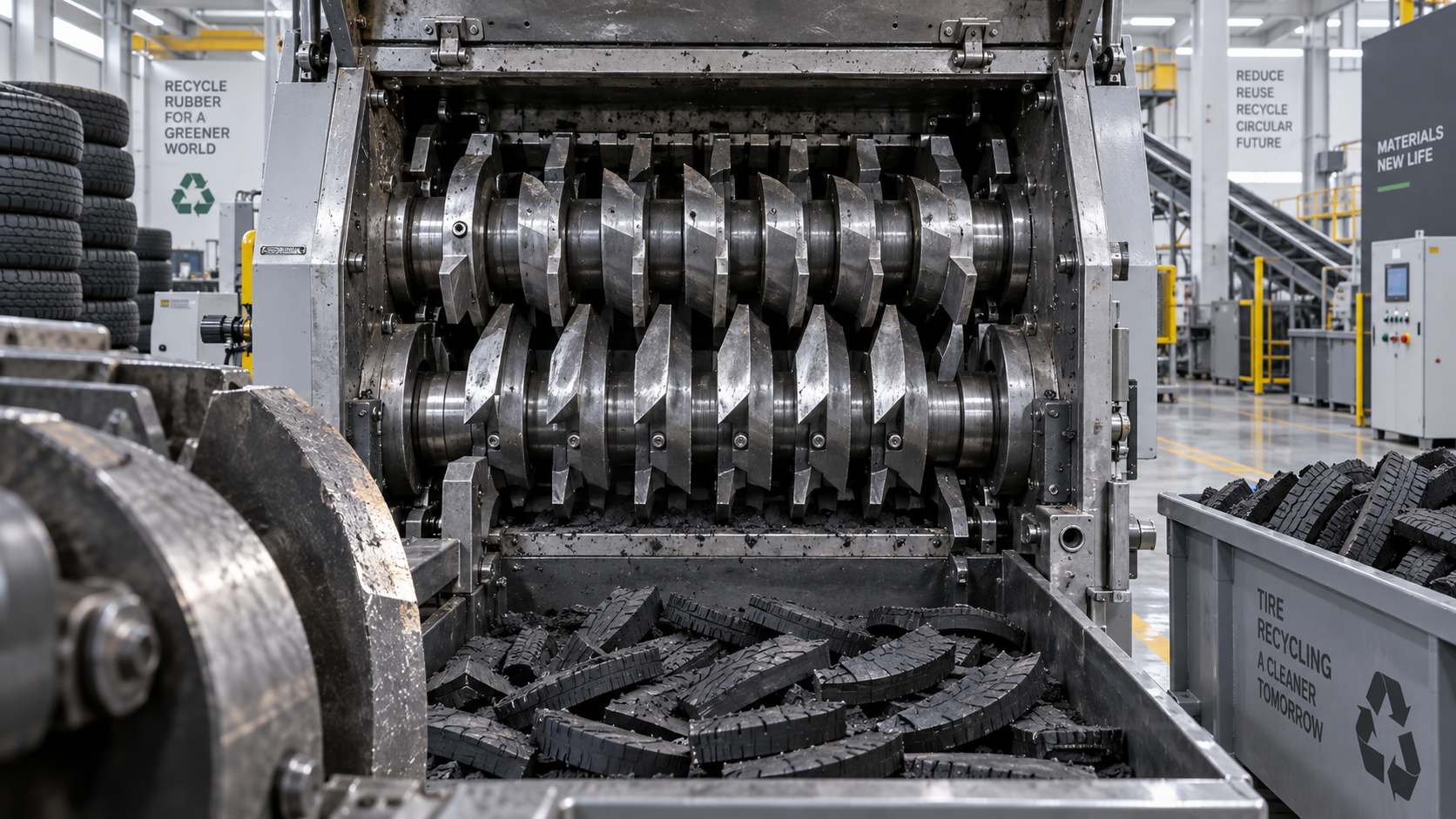
Rubber vulcanizing presses require analysis of closing movement, high-temperature molds, curing fumes, trapped pressure, and access during loading or unloading. Blow molding machinery can combine high-speed clamping, heated parisons, compressed-air systems, trimming stations, and automated part transfer. The risk assessment should record reasonably foreseeable misuse, such as bypassing an interlocked guard during a jam, reaching into a feed throat to clear a bridge, or opening a hot die before pressure has dissipated.

Protective measures should follow a defensible hierarchy. Inherently safer design may reduce reachable nip points, lower accessible surface temperatures, or place routine adjustments outside hazardous zones. Guards and interlocks then address remaining exposure. Information for use is necessary, but a warning label cannot compensate for a guard that is impractical to remove, a control layout that invites unsafe recovery work, or a stopping time that leaves hazardous motion after access is possible.
Safety functions need verifiable design evidence
Safety-related control functions deserve separate attention because they connect mechanical design, electrical design, software, and validation. Typical functions include emergency stop, guard interlocking, prevention of unexpected restart, two-hand control where applicable, safe speed during setup, motor torque removal, overpressure shutdown, and temperature-limit protection. Each function should have a documented safety requirement: the initiating event, expected machine response, reset conditions, diagnostic behavior, and foreseeable fault response.
An emergency-stop device is not necessarily a means of energy isolation. A line may need a controlled stop to avoid material degradation or equipment damage, but isolation procedures still need to address electrical supply, hydraulic accumulators, pneumatic pressure, gravity, hot melt, and stored mechanical energy. Instructions should distinguish a production stop, an emergency stop, a maintenance isolation procedure, and a controlled purge procedure. Combining them under one vague instruction creates avoidable ambiguity.
Validation records should test the delivered logic, including wiring changes made during assembly. Tests commonly cover every emergency-stop device, each guard door and removable guard, reset behavior after a protective device is activated, restart after power restoration, mode selection, and safety outputs connected to related equipment. Where programmable controls are used, version identification and backup control are important. A software change can alter a validated function even when no mechanical component has moved.
Technical documentation is a controlled evidence set
The technical file is generally retained by the responsible economic entity and may not travel with every machine. It should nevertheless be complete enough to demonstrate the basis for conformity if requested. Its contents commonly include a general machine description, drawings, layouts, electrical and pneumatic or hydraulic diagrams, control-system information, a risk assessment, applied standards or other technical specifications, calculations where relevant, test reports, component declarations, and copies of supplied instructions and declarations.
For high-pressure melt systems, the file should identify pressure-rated components, relief arrangements, transducer ranges, alarm thresholds, and the basis for their selection. For heaters and temperature controllers, it should describe independent temperature limitation where required by the risk analysis, sensor failure behavior, alarm response, and accessible hot-surface controls. On equipment processing PVC, filled compounds, recycled feedstock, rubber mixes, or additives with specific thermal behavior, intended material limits should be stated clearly rather than assumed from the machine's general name.
Drawings need revision status and a direct relationship to the equipment serial number or configuration record. A documentation package can fail during an audit because the electrical schematic shows one safety relay while the panel contains another, or because the guarding drawing omits a field-installed access gate. Revision control should capture mechanical modifications, replacement of safety components, changes to electrical architecture, software revisions, and updates to the declared intended use.
The Declaration of Conformity should identify the machine sufficiently to prevent confusion between product variants. It normally includes the responsible entity, machine identification, relevant legal references, applicable standards or specifications where cited, and the authorized signature details required by the applicable framework. It should not be issued casually for a machine awaiting essential guarding, unfinished integration, or unvalidated safety functions. Where the supply status is genuinely partly completed machinery, the appropriate accompanying declaration and assembly information should reflect that status instead.
Instructions must match work at the machine
Operating instructions are part of the conformity evidence, not a sales attachment. They need to be understandable in the language requirements applicable to the destination market and specific enough for the delivered equipment. Generic manuals often fail at the exact points where risk is highest: die changes, screw removal, screen replacement, barrel cleaning, mold installation, cutter maintenance, jam clearing, and recovery after a trip.
A robust manual states the rated materials and operating limits, including temperature ranges, pressure limits, permitted mold or die mass where relevant, electrical supply requirements, compressed-air requirements, cooling-water conditions, extraction needs, floor loading assumptions, and environmental limitations. It should explain how to verify protective devices before operation, how to isolate all energy sources, how long components may remain hot, and how residual pressure is safely released.
Maintenance instructions should avoid broad phrases such as “ensure the machine is safe.” A clearer procedure identifies the isolation points, locking method, verification of zero energy, cooling requirement, bleed-down location, necessary personal protective equipment, and conditions for restoring energy. For a screen changer or die assembly, this may include a written confirmation that melt pressure has been relieved before bolts are loosened. For a granulator, it may require confirmation that the rotor has stopped and cannot rotate due to stored kinetic energy or back-driving.
Installation can change the original compliance position
Transport and installation are common sources of undocumented deviation. Equipment may be separated into modules for shipping, then reassembled with local guards, cable trays, extraction ducting, platforms, or added conveyors. These additions can affect access distances, escape routes, electrical protection, noise exposure, and emergency-stop reach. Installation records should show that anchoring, leveling, earth bonding, utility connections, safety-circuit interfaces, and commissioned protective devices match the installation drawings.
Field modifications require the same discipline as factory changes. Replacing a fixed guard with mesh of a different opening size, adding a robot cell, increasing extruder motor capacity, extending a conveyor, or changing the control mode can introduce hazards beyond the original assessment. The change should be evaluated before release to production, with updated drawings, risk controls, tests, and instructions where necessary. The CE mark on the original machine does not automatically cover every later alteration.
Common documentation and safety failures
- A declaration identifies a generic machine family, while the supplied equipment includes unrecorded automation and a different control architecture.
- Interlocked access doors stop one drive but allow adjacent hazardous movement to continue within the accessible zone.
- Manuals describe normal operation yet give no controlled method for clearing blocked feed material, purging a barrel, or changing a hot die.
- Electrical drawings list safety devices but provide no evidence that final installed functions were validated after commissioning.
- Warnings are used in place of physical protection around rotating screws, cutters, closing platens, or hot melt discharge points.
CE marking remains credible when the physical safeguards, control behavior, declaration, risk assessment, drawings, and instructions all point to the same defined machine. For plastic processing equipment, that consistency must survive configuration changes, shipment, installation, and the demanding realities of hot materials, moving tools, pressure, and continuous production.
Related News
- 00
0000-00
PET Pelletizing Equipment: Strand vs. Underwater Systems for Recycled PET - 00
0000-00
Tire Manufacturing Equipment: Choosing Curing Presses by Tire Size and Output - 00
0000-00
How continuous filtration handles contaminants in plastic recycling - 00
0000-00
Where drying fits in the PET plastic recycling plant process - 00
0000-00
What Drives Underwater Pelletizing System Cost in High-Throughput Compounding?
Weekly Insights
Stay ahead with our curated technology reports delivered every Monday.
Related News
 Ms. Elena RodriguezSmart Factory Costs for Plastics: Estimating ROI for Automation ProjectsSmart factory for plastics cost: learn how to estimate automation ROI, uncover hidden integration expenses, reduce scrap, and build a phased investment plan.Oct 10, 2026
 Ms. Elena RodriguezHow to Evaluate a Packaging Molding Equipment Supplier for High-Volume ProductionChoose a packaging molding equipment supplier with confidence. Learn how to assess throughput stability, tooling, recycled-material capability, lifecycle cost, and service support for high-volume production.Oct 09, 2026
 Ms. Elena RodriguezHow to Select Packaging Molding Equipment for High-Volume Production LinesPackaging molding equipment selection guide for high-volume lines: compare processes, throughput, materials, automation, and energy to achieve stable, cost-effective output.Oct 04, 2026
 Ms. Elena RodriguezHow to Evaluate Plastic Recycling Machinery for UAE Heat, Feedstock, and Output NeedsPlastic recycling machinery UAE buyers: evaluate heat resilience, feedstock handling, cooling, pellet quality, energy use, and lifecycle cost for reliable output.Sep 28, 2026
 Ms. Elena RodriguezGerman Extrusion Equipment Suppliers: Comparing Service, Lead Times, and Lifecycle CostExtrusion equipment Germany suppliers compared: evaluate service coverage, credible lead times, spare-parts access, and lifecycle cost to select a reliable, future-ready production partner.Sep 22, 2026
 Ms. Elena RodriguezWhat Should You Check Before Buying a Used Plastic Recycling Line?What should I check before buying a used plastic recycling line? Explore feedstock fit, wear, trials, utilities, controls, and restoration costs before you invest.Sep 26, 2026
 Ms. Elena RodriguezHow to Compare Pelletizing Lines by Energy Use per TonHow do I compare pelletizing lines by kWh per ton? Learn to measure total energy, verify saleable output, and select a cost-efficient line.Sep 23, 2026
 Ms. Elena RodriguezTyre Cutter Blade Wear: When Capacity Loss Needs Inspectionшинорез blade wear can quietly reduce tyre-cutting capacity. Learn the warning signs, inspection triggers, and maintenance actions that protect output and uptime.Sep 28, 2026
 Ms. Elena RodriguezIn-House Recycling for Factory Scrap: How to Reduce Material Waste and Disposal CostsIn house recycling for factory scrap helps manufacturers cut material waste, reduce disposal costs, and create controlled, quality-focused reuse loops.Sep 07, 2026
 Ms. Elena RodriguezHow Recyclable Packaging Manufacturing Balances Material Recovery and Production CostRecyclable packaging manufacturing: discover how smarter design, feedstock control, and process optimization reduce recovery costs while improving quality and yield.Sep 04, 2026
 Ms. Elena RodriguezHow to Evaluate a Plastic Recycling Systems Supplier for Your Processing NeedsChoose the right plastic recycling systems supplier with a practical guide to feedstock fit, output quality, total cost, testing, service, and compliance.Sep 01, 2026
 Ms. Elena RodriguezCE Marking for Plastic Processing Equipment: Documentation and Safety ChecksPlastic processing equipment CE compliance: learn the essential documentation, risk assessments, safety checks, and validation steps for reliable EU market access.Aug 30, 2026
 Ms. Elena RodriguezPlastic Packaging Compliance Standards: What Tests and Documents Matter Most?Plastic packaging compliance standards explained: learn which migration tests, mechanical checks, and audit-ready documents matter most to reduce risk and pass reviews with confidence.Aug 25, 2026
 Ms. Elena RodriguezHow to Evaluate a Plastic Waste Recycling System for Capacity, Contamination, and ROIPlastic waste recycling system evaluation made practical: compare true capacity, contamination control, and ROI to choose a line that delivers stable output and stronger returns.Aug 24, 2026
 Ms. Elena RodriguezPackaging Molding Equipment Price: What Drives Cost and How to Compare Quotes?Packaging molding equipment price varies by machine type, automation, tooling, energy use, and service scope. Learn what drives cost and how to compare quotes with confidence.Aug 21, 2026
 Ms. Elena RodriguezWhat Packaging Machinery for Plastic Containers Should You Choose for High-Volume Production?Packaging machinery for plastics containers can make or break high-volume production. Learn how to choose the right line for speed, consistency, compliance, and lower lifecycle costs.Aug 16, 2026
 Ms. Elena RodriguezWhat Circular Plastics Mean for Automotive Parts and Material SelectionCircular plastics for automotive are reshaping part selection with lower weight, better sustainability, and reliable performance. Discover how engineers balance recycled content, durability, and compliance.Aug 15, 2026
 Ms. Elena RodriguezBroiler Farming in Cage System: Selection Factors for Commercial FarmsBroiler farming in cage system selection for commercial farms: compare structure, ventilation, automation, and manure handling to improve efficiency and avoid costly mistakes.Aug 14, 2026
 Ms. Elena RodriguezHow to Implement Smart Polymer Manufacturing Without Disrupting Existing Production?Smart polymer manufacturing implementation made practical: learn how to upgrade existing production with phased digitalization, less downtime, better control, and measurable ROI.Aug 11, 2026
 Ms. Elena RodriguezHow to Evaluate a Rubber Compression Molding Supplier for Complex Part ProductionRubber compression molding supplier selection for complex parts starts with process, material, and tooling control. Learn how to compare vendors beyond price and reduce launch risk.Aug 10, 2026