What causes pellet agglomeration in plastic underwater pelletizing?




What causes pellet agglomeration in plastic underwater pelletizing?
Pellet clumps in plastic underwater pelletizing can interrupt conveying, overload dryers, and create feeding problems in downstream extrusion or molding. The basic mechanism is simple: pellets touch while their surfaces are still soft enough to bond. Finding the reason is less straightforward. Inadequate cooling, excessive melt temperature, restricted water circulation, and poor cutting can produce similar symptoms.
The most useful starting point is not “Which setting should we change?” but “Where do the clumps first appear?” Fused pellets leaving the cutting chamber require a different investigation from pellets that leave the dryer separately but stick together in a storage bin. Locating that first point prevents unnecessary adjustments to otherwise stable equipment.
Why freshly cut pellets stick together
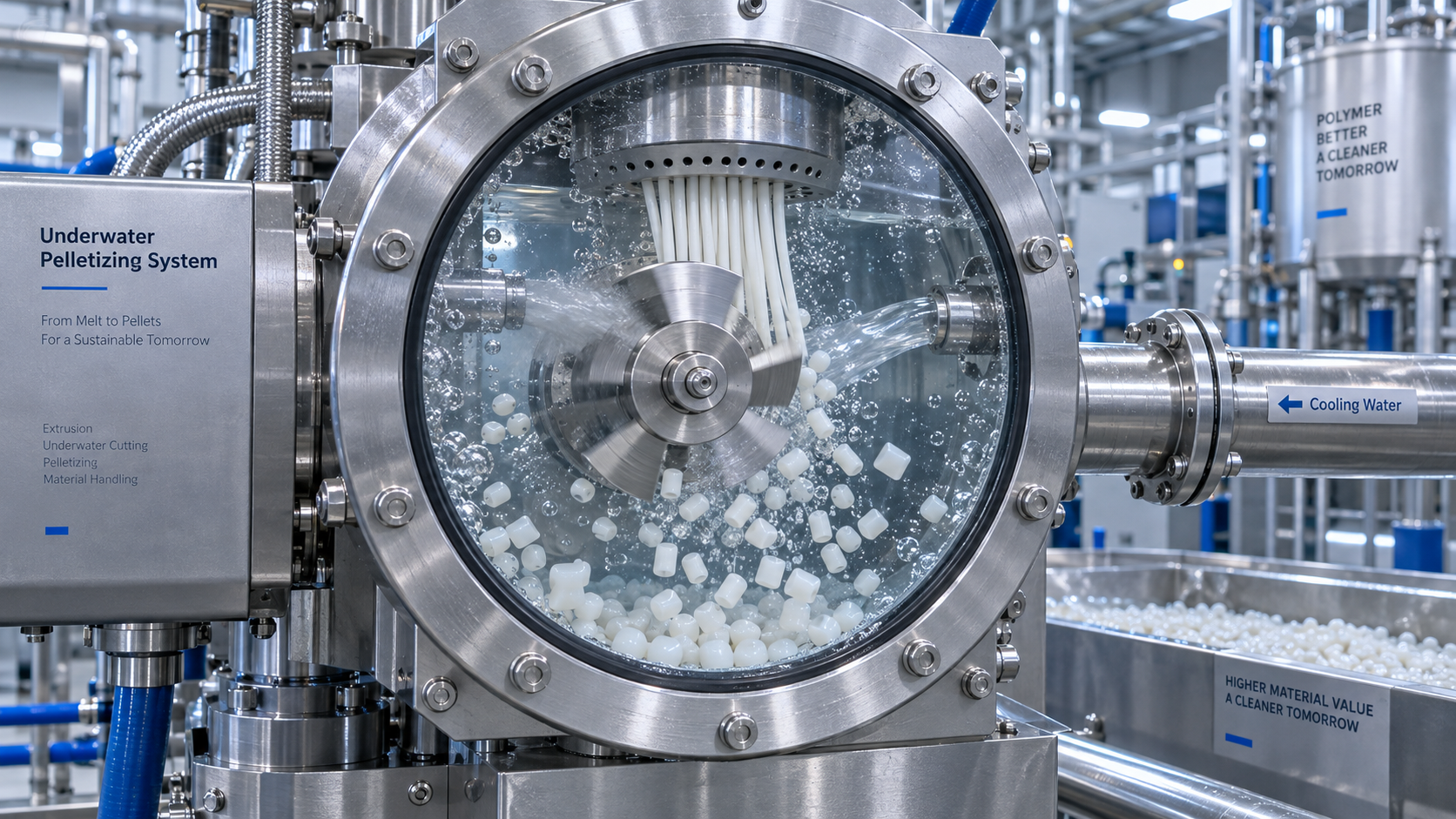
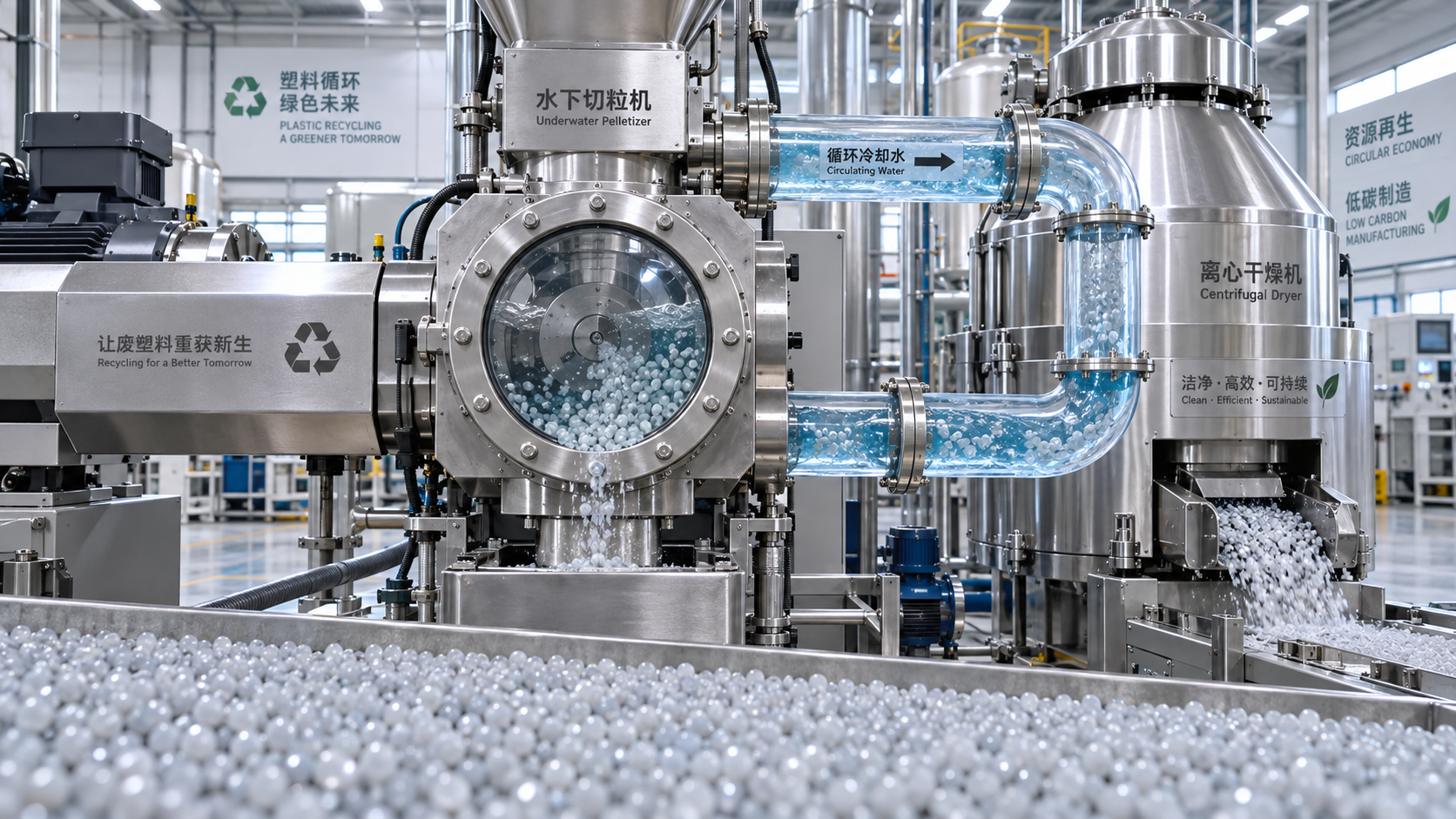
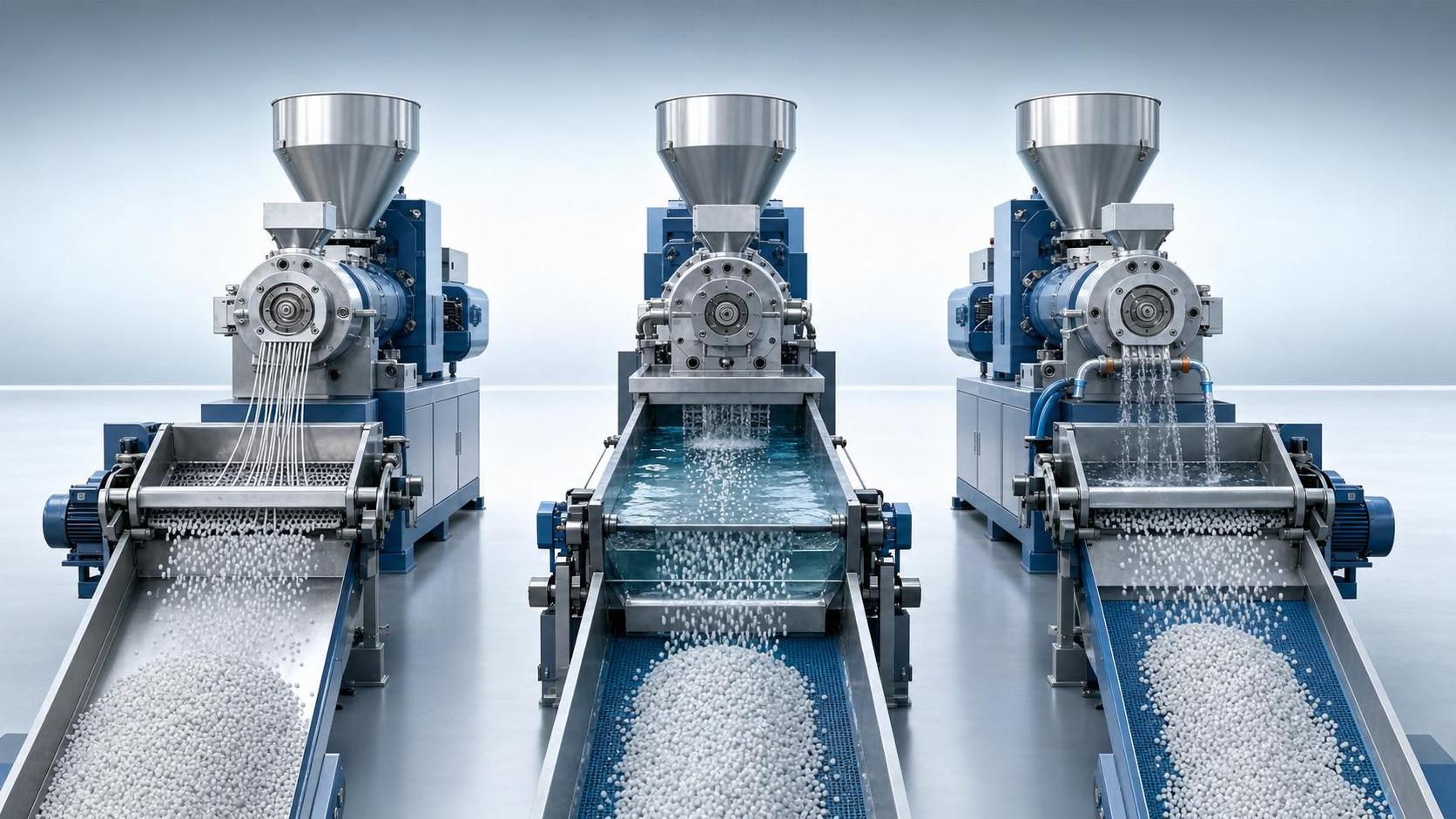
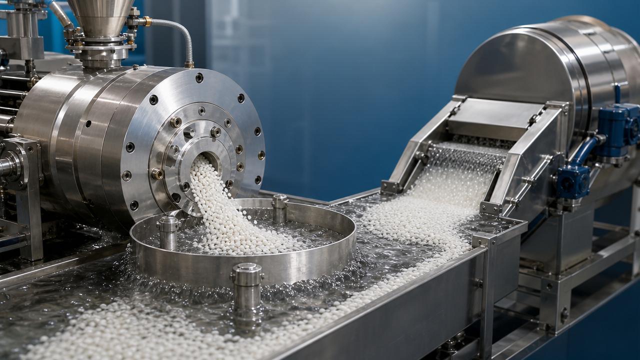
An underwater pelletizer cuts molten polymer at the die face while circulating water removes heat and carries pellets away. Successful operation depends on balancing three things: clean separation at the blade, rapid surface solidification, and enough transport capacity to keep soft pellets from accumulating.
A pellet can develop a firm outer skin while retaining a hot core. That distinction matters. Pellets may look acceptable in the water loop but soften again as internal heat moves toward the surface after dewatering. For semicrystalline polymers, crystallization behavior also affects how quickly the pellet develops sufficient mechanical stability.
Not every cluster is a fused agglomerate. Pellets can also become mechanically entangled by tails or joined by incompletely severed material. Wet pellets may form loose clusters without permanent bonding. Examine cooled samples: welded contact points, stretched bridges, and clusters that separate easily point toward different causes.
Locate the first abnormal sample
Use designated sampling points to compare pellets as close to the cutting chamber as safely possible, at the dryer inlet, at the dryer discharge, and after any intermediate storage. Follow site procedures; never open pressurized water lines or access rotating equipment to obtain a sample.
- Clumps already present near the cutter: investigate melt condition, blade performance, local water movement, and die-face buildup.
- Clumps first found farther along the slurry line: check restricted transport, excessive pellet concentration, and places where pellets can collect.
- Clumps appearing at dryer discharge: compare inlet samples and inspect dryer loading, deposits, and pellet temperature.
- Blocking only after storage: investigate residual heat, surface tack, storage temperature, and pressure from the pellet bed.
This sequence narrows the investigation, but it does not prove the cause by itself. A large clump found at the dryer may have formed upstream and simply become trapped there.
Cooling problems: temperature alone does not tell the full story
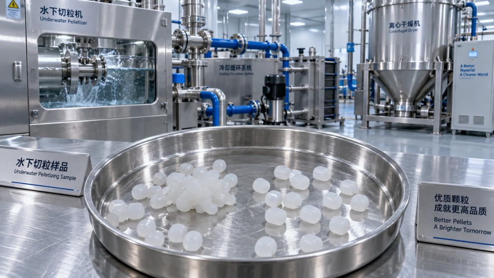
Warm process water reduces the temperature difference driving heat transfer from polymer to water. When throughput increases, the water circuit must absorb more heat. A system that works at a lower production rate may gradually lose cooling capacity at higher output, especially with a fouled heat exchanger or limited utility cooling.
Check actual supply and return water temperatures under load, not just the controller setpoint. A rising supply temperature during an otherwise steady run suggests that heat removal is not keeping pace. Inspect heat-exchanger condition, cooling-side availability, and control-valve operation before assuming the pelletizer needs different settings.
Water flow has a separate job: clearing pellets from the cutting zone. Low flow can leave newly cut pellets crowded near the die, where repeated contact encourages bonding. Possible causes include clogged strainers, restricted valves, pump problems, or deposits in the piping. Pump speed or discharge pressure alone does not establish the delivered flow through the cutting chamber.
However, “make the water colder” is not a universal solution. Excessive cooling at the die can promote hole freeze-off, depending on polymer and die design. Fewer flowing holes redistribute output through the remaining holes, changing pellet size and cutting conditions. Use the resin supplier’s guidance and the equipment manufacturer’s operating window rather than a generic temperature target.
Excessive melt heat and unstable die discharge
Higher melt temperature increases the heat that must be removed before pellets resist sticking. It can also change viscosity and the way polymer separates from the die face. Barrel settings are only part of the picture: screw shear, restriction through filtration, and residence time can affect actual melt temperature.
Compare measured melt temperature near the pelletizing die with the validated range for the grade. Check whether agglomeration coincides with a screw-speed increase, screen change, pressure rise, or formulation adjustment. A heater display showing the normal setpoint does not rule out a hotter melt.
Avoid lowering every heating zone at once. An excessively cool or poorly homogenized melt can increase pressure, disturb die flow, and make cutting less consistent. The objective is a stable melt at an appropriate processing temperature, not simply the lowest possible temperature.
Pressure and discharge fluctuations also deserve attention. Surging changes the amount of polymer presented to each blade pass, producing variable pellet sizes. Larger pellets retain heat longer, while irregular pieces can bridge or lodge in the transport system.
When cutting defects become agglomeration
Cooling cannot fully compensate for pellets that were never cleanly separated. Worn blades, uneven blade contact, die-face damage, or incorrect cutter alignment can leave tails and connected pieces. Polymer smeared across the die face may collect additional material and release as larger masses.
Inspect pellet shape before changing cutter speed. Repeated tails, flattened pieces, or linked pellets justify checking blade condition and the manufacturer-specified contact or loading arrangement. Mechanical inspection requires the prescribed shutdown, isolation, and lockout procedure.
Cutter speed must match throughput, blade count, and the number of actively flowing die holes. Increasing speed generally reduces material cut per blade pass under otherwise stable conditions, but it is not a cure for worn blades or blocked holes. Excessive speed can introduce other quality problems, including fines, depending on the resin and equipment.
If pellet size suddenly changes despite unchanged throughput and cutter speed, investigate the die-hole flow pattern. The nominal hole count is less useful than the number actually passing polymer.
Resin changes can narrow the operating window
A setting that works for one grade may fail for another. Soft thermoplastic elastomers and tacky formulations can require different cooling and handling conditions from more rigid grades. Additives, plasticizers, and polymer blends may alter surface behavior even when the pellets appear visually similar.
Recycled feedstocks add variability. Changes in polymer composition, melt flow, contamination, or additive history can affect melt behavior and pellet solidification. This does not mean recycled material inevitably agglomerates; it means a previously successful recipe needs to be checked against the incoming material.
When clumping follows a feedstock-lot change, preserve samples from both lots and compare available quality records. Melt-flow results can help identify a shift, but they do not describe surface tack or solidification behavior completely. Grade-specific guidance or appropriate laboratory characterization may be needed for persistent problems.
Do not overlook transport, drying, and storage
Slurry transport must move pellets without allowing sustained accumulation. Restricted sections, unsuitable piping geometry, or deposits can create locations where soft pellets remain in contact. Increasing throughput without reviewing water circulation raises pellet concentration and may expose a limitation that was previously hidden.
Check differential pressure where instrumentation is available and inspect strainers and piping during planned maintenance. Increasing water flow blindly can overload downstream equipment; the cutter, transport line, and dryer must remain within their respective limits.
At the dryer, examine screens, internal deposits, discharge restrictions, and loading. A centrifugal dryer primarily removes surface water; it should not be assumed to cool the pellet core sufficiently for storage. If separate pellets become fused only after drying or in a bin, measure discharge temperature and investigate the subsequent cooling and handling arrangement.
Loose wet clusters and thermally bonded clumps need different corrections. Extra drying may address residual surface water, but it will not necessarily solve heat-driven blocking. A long residence time under pressure in a warm storage bin can reveal tack that was not obvious at discharge.
A controlled way to restore stable production
Before adjusting the process, record the resin lot, throughput, actual melt temperature, die pressure, cutter speed, water temperatures, measured water flow, and the earliest location showing clumps. Include pellet shape and whether the defect began during startup, after a rate increase, or after prolonged operation.
That timing is useful evidence. Startup-only clumps suggest a sequencing or stabilization issue worth checking against the manufacturer’s procedure. Clumping after a sustained run warrants attention to heat accumulation or progressive restriction. A defect immediately following a material change points toward formulation compatibility or a changed processing window.
Change one relevant variable at a time and allow the system to stabilize before evaluating samples. Where permitted by operating procedures, a controlled throughput reduction can help determine whether cooling or transport capacity is limiting production. Do not keep compensating with settings when inspection indicates blade wear, blocked flow paths, or failing equipment.
For Global Polymer Forming & Recycling Systems (PFRS), connecting polymer behavior with extrusion, recovery, and downstream manufacturing is central to useful process intelligence. Here, that means judging a correction by more than cleaner-looking pellets: dryer loading, fines, energy demand, and downstream feeding should remain acceptable too.
Once stable operation returns, document the grade-specific operating window and the warning signs that preceded the defect. If agglomeration persists, give the equipment or resin supplier synchronized process readings and samples from successive locations. That evidence is far more actionable than reporting only that “the pellets are sticking.”
Related News
- 00
0000-00
Injection Molding System Costs: Machine, Molds, Automation, and Installation - 00
0000-00
Truck Tire Manufacturing Equipment: Sizing Curing Presses for Target Output - 00
0000-00
How Single-Use Plastic Bans Shift Demand for Packaging Materials - 00
0000-00
PET Pelletizing Equipment: Strand vs. Underwater Systems for Recycled PET - 00
0000-00
Tire Manufacturing Equipment: Choosing Curing Presses by Tire Size and Output
Weekly Insights
Stay ahead with our curated technology reports delivered every Monday.
Related News
 Circular Plastics ExpertStrand pelletizing vs underwater pelletizing for frequent grade changesStrand pelletizing vs underwater pelletizing: compare cleaning, restart stability, and material losses for frequent grade changes. Find the right system to cut downtime and boost saleable output.Oct 17, 2026
 Circular Plastics ExpertWhat causes pellet agglomeration in plastic underwater pelletizing?Plastic underwater pelletizing clumps? Discover how cooling, melt temperature, cutting defects, and handling cause agglomeration—and learn practical checks to restore stable production.Oct 17, 2026
 Circular Plastics ExpertHow melt viscosity affects polymer underwater pelletizingImprove polymer underwater pelletizing by understanding melt viscosity. Discover how to balance die pressure, cutting, and cooling for fewer defects and more uniform pellets.Oct 16, 2026
 Circular Plastics ExpertSizing an underwater pelletizing line for recycled plastic outputSize an underwater pelletizing line for plastics to meet recycled output targets. Learn how feedstock, filtration, cooling, and drying affect capacity—and compare suppliers with confidence.Oct 16, 2026
 Circular Plastics ExpertWhat Drives Underwater Pelletizing System Cost in High-Throughput Compounding?Underwater pelletizing systems cost depends on throughput, material wear, automation, water treatment, and lifecycle needs. Learn how to compare quotes for reliable compounding performance.Oct 12, 2026
 Circular Plastics ExpertIs an Underwater Pelletizer Worth the Added Cost for Recycled Plastics?Is an underwater pelletizer worth the extra cost for recycled plastics? Compare quality, uptime, fines, and ROI to choose the right pelletizing solution.Sep 25, 2026
 Circular Plastics ExpertWhen Is Underwater Pelletizing for Bioplastics the Right Choice?Underwater pelletizing for bioplastics is the right choice when weak strands, sticky melts, or tight pellet specs challenge output. Learn when it improves quality, stability, and scale-up.Aug 09, 2026
 Circular Plastics ExpertHow to Evaluate Pelletizing Equipment in Germany for Throughput, Energy Use, and SupportPelletizing equipment Germany buyers compare needs more than nameplate output. Learn how to verify real throughput, energy use, maintenance costs, and local support before you invest.Aug 08, 2026
 Circular Plastics ExpertHow to Evaluate High Output Plastic Pelletizing Machines for Stable Capacity and Pellet QualityHigh output plastic pelletizing machines should be judged by stable throughput, pellet quality, filtration, and energy use. Learn how to compare systems for reliable recycling performance.Jul 21, 2026
 Circular Plastics ExpertPlastic Pelletizing Machines Price Breakdown: What Drives CapEx and Operating Cost?Plastic pelletizing machines price explained: compare CapEx, energy, labor, wear parts, and uptime to see what truly drives total cost and smarter recycling ROI.Jul 15, 2026
 Circular Plastics ExpertWaste Plastic Pelletizing Line Selection: Output, Energy Use, and Contamination ControlWaste plastic pelletizing line selection affects output, energy cost, and pellet quality. Learn how to match feedstock, cut contamination, and improve ROI.Jul 09, 2026
 Circular Plastics ExpertUnderwater Pelletizing in Japan: Why Process Control Matters for Uniform Pellet QualityUnderwater pelletizing Japan demands precise process control for uniform pellet quality, lower fines, and stable output. See how better control improves safety, compliance, and plant reliability.Jul 04, 2026
 Circular Plastics ExpertHow to Choose Plastic Pelletizing Machines for PET: Output, IV Retention, and Melt QualityPlastic pelletizing machines PET buyers can trust should balance output, IV retention, and melt quality. Learn how to compare PET recycling lines for stable pellets and better ROI.Jul 03, 2026
 Circular Plastics ExpertPlastic Pelletizing Methods Compared: Strand, Underwater, and Water-Ring SystemsPlastic pelletizing compared: explore strand, underwater, and water-ring systems to choose the best fit for pellet quality, throughput, cost, and efficient production.Jun 29, 2026
 Circular Plastics ExpertPlastic Pelletizing Machines Price: What Factors Affect Cost and ROI?Plastic pelletizing machines price depends on capacity, automation, energy use, and service. Learn what drives cost, compare offers wisely, and improve ROI faster.Jun 26, 2026
 Circular Plastics ExpertUnderwater Pelletizing Technology vs Strand Pelletizing: Which Materials Fit Best?Underwater pelletizing technology vs strand pelletizing: discover which materials perform best, how pellet quality and throughput differ, and which system can cut cost and boost uptime.Jun 25, 2026
 Circular Plastics ExpertHow Underwater Pelletizing Technology Works and Which Polymers It Fits BestUnderwater pelletizing technology explained: learn how it works, which polymers it fits best, and how it improves pellet quality, recycling efficiency, and line stability.Jun 23, 2026
 Circular Plastics ExpertHow to Choose a Pelletizing Equipment System for Output, Resin Type, and Plant SpacePelletizing equipment system selection starts with output, resin type, and plant space. Discover practical tips to improve pellet quality, uptime, and long-term efficiency.Jun 21, 2026
 Circular Plastics ExpertHow Continuous Underwater Pelletizing Systems Work and Which Materials They Handle BestContinuous underwater pelletizing systems explained: learn how they work, which polymers and recycled materials they handle best, and when they outperform strand pelletizing for stable output.Jun 16, 2026
 Circular Plastics ExpertHow to Choose Plastic Pelletizing Equipment for Output, Material, and Pellet QualityPlastic pelletizing equipment selection depends on output, material behavior, and pellet quality. Compare methods, hidden cost factors, and practical criteria to choose the right system.Jun 13, 2026