What causes unstable melt pressure in compounding extruders




Pressure fluctuation is a process warning, not just a gauge problem
Unstable melt pressure in a compounding line deserves prompt attention because pressure is a direct expression of how material is moving through the screws, melt channels, screen pack, die, and downstream equipment. A drifting or cycling pressure signal can precede visible quality defects, but by the time pellets, strand, sheet, or profile output looks inconsistent, the process may already have experienced poor mixing, unstable residence time, overheating, or intermittent restriction.
The most useful first distinction is between a real process fluctuation and a bad measurement. If the melt pressure trace changes in a repeatable pattern while motor load, feeder rate, melt temperature, or output also changes, the extrusion process is likely unstable. If the pressure indication jumps while the rest of the line appears steady, inspect the sensor, wiring, impulse path, and data acquisition before changing screw speed or barrel settings. Operators can lose hours trying to correct a process that is not actually moving.
For most compounding extruders, pressure instability comes from one of four areas: inconsistent material entering the screws, changing melt viscosity inside the barrel, growing or intermittent resistance downstream, or unsuitable operating conditions for the screw and die configuration. The pressure signal identifies that a balance has been disturbed. Finding the cause requires comparing it with the rest of the line rather than treating pressure as an isolated number.
Start by reading the pattern of the pressure signal
A pressure trend often provides better diagnostic value than a single average reading. A slow, steady rise may indicate screen-pack loading, die buildup, or a gradual change in material viscosity. A repeating wave can point to cyclic feeding, screw pulsation, poor solids conveying, or temperature-control hunting. Sharp drops followed by recovery may occur when a partially blocked die or screen pack clears temporarily, when a bridge in the feeder collapses, or when a side feeder intermittently delivers material.
Before making a correction, record the same time window for melt pressure, screw speed, main motor torque or current, feeder rates, barrel-zone temperatures, melt temperature where available, vacuum level, and throughput. This does not require a complex analysis system. Even a short synchronized record can establish whether the pressure problem begins upstream at feeding or downstream at the die.
A useful rule for troubleshooting is to avoid changing several inputs at once. Raising barrel temperatures, increasing screw speed, and changing feeder settings may temporarily suppress the symptom while making the root cause harder to identify. Make one controlled adjustment, allow the line to respond over an appropriate residence-time interval, and compare the pressure trace again.
Inconsistent feeding is often the first place to look
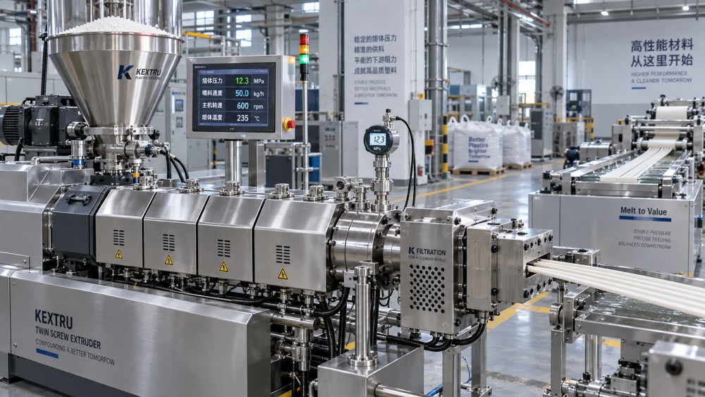
A twin-screw compounding process can only build stable pressure if mass flow into the extruder is stable. This sounds obvious, but feed inconsistency is often hidden by a feeder display that reports a correct average rate. The extruder reacts to short-term pulses, starvation, bridging, segregation, and poor refill behavior, not simply to the average kilograms per hour logged at the end of a batch.
Loss-in-weight feeders should be checked for refill transitions, material build-up on the hopper wall, poor agitation, unstable bulk density, and calibration drift. Fine powders may compact or rat-hole. Low-bulk-density fibers can bridge. Pellets mixed with powders or mineral fillers can segregate during handling, allowing the composition delivered to the screws to change even when the total feed rate appears stable. Regrind and recycled feedstock add another layer of variation because flake size, fines content, contamination, and residual moisture can vary across a container or lot.
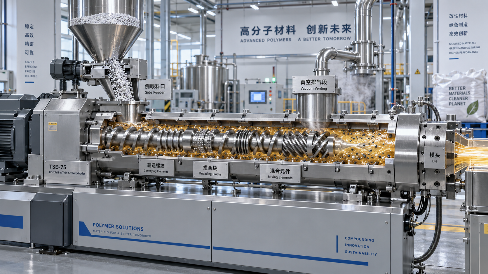
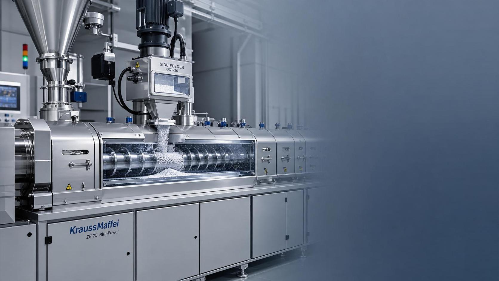
Side feeding deserves separate attention. A side feeder that alternates between overfilling and starving can create a delayed pressure response as the material is incorporated and melted downstream. If the pressure cycle matches the side feeder’s apparent delivery cycle, investigate screw fill, hopper geometry, feeder speed control, and the point at which material is introduced. A poorly filled side feeder may also allow melt to back up toward the feed port, causing further instability and possible material accumulation.
Feed instability cannot always be corrected by increasing main screw speed. Higher speed may reduce average fill and mask a pressure peak, but it can also increase shear heating, shorten residence time, or worsen the effect of a pulsing feeder. Stabilize the incoming mass flow first, then establish the screw speed needed for the required dispersion and output.
Moisture, contamination, and material variability change melt behavior
Pressure is strongly affected by viscosity, and viscosity is affected by material condition. A resin that appears to be the same grade may process differently when moisture content, additive concentration, molecular degradation, particle geometry, or contamination changes. Operators should be especially cautious after a new material lot, a formulation change, a recycled-content increase, or a long production interruption.
Moisture can cause several kinds of instability. In hygroscopic polymers, inadequate drying may promote hydrolytic degradation during processing, lowering molecular weight and altering viscosity. In other materials, water may flash into vapor, disturb conveying and venting, or create pressure fluctuations near restrictive downstream components. A pressure reduction caused by degradation may be mistaken for improved flow, while the finished compound loses mechanical performance or shows defects later in molding or extrusion.
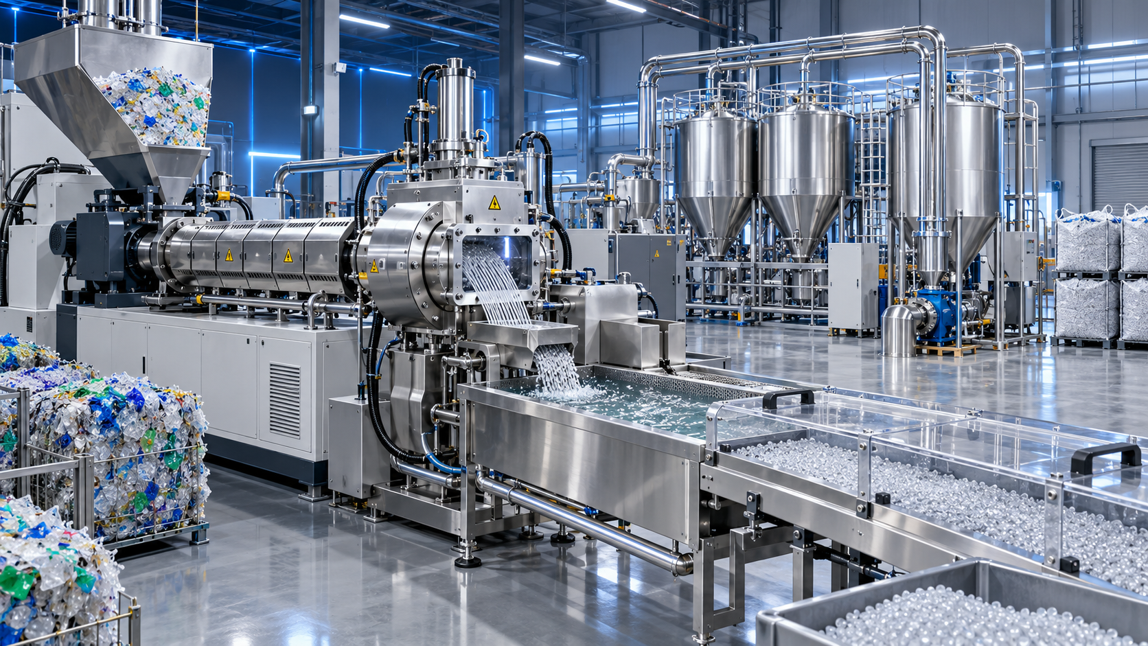
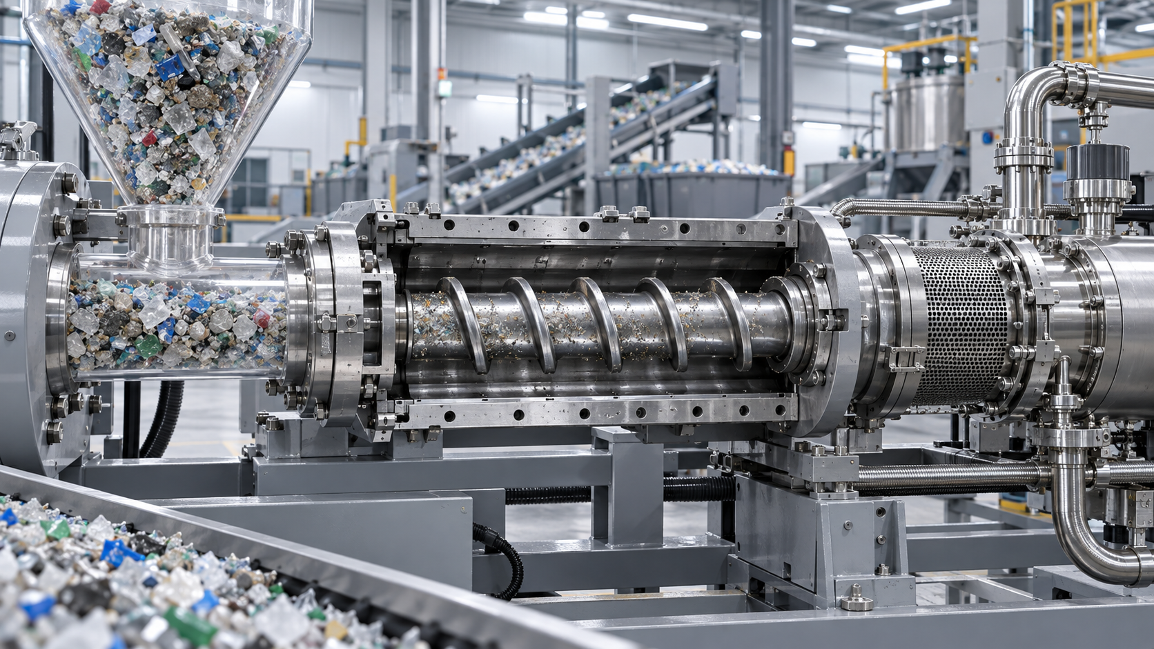
Recycled streams require particular discipline because the source of pressure variation may be physical rather than purely chemical. Paper, aluminum fragments, adhesive residues, wood, elastomer particles, unmelted high-melting polymer, and excessive fines can create intermittent restrictions at screens and dies. Residual detergent, moisture, or volatile contamination may affect degassing and melt consistency. The response should begin with material inspection and separation performance, not an assumption that every fluctuation is a barrel-temperature issue.
Material temperature at the point of feeding also matters. Cold pellets, warm regrind, and material stored in humid conditions can produce different conveying and melting behavior. When troubleshooting, compare actual feedstock condition across shifts and containers. A stable formulation on paper does not guarantee a stable feed stream at the hopper.
Barrel temperatures must support the screw design and the material’s melting path
Temperature settings are frequently adjusted first because they are easy to change. They are also easy to misuse. A barrel profile is not simply a set of numbers that should be raised whenever pressure is high or lowered whenever pressure is low. In compounding extruders, the material is heated by barrel zones, mechanical shear, compression, and viscous dissipation. The melt condition at the pressure sensor reflects all of those inputs.
Too little heat in an early melting section can leave solids or poorly softened particles entering high-shear elements. Torque and pressure may then fluctuate as the screws alternately compact, melt, and release material. Excessive temperature, especially in highly filled or shear-sensitive formulations, can lower viscosity too far, increase degradation risk, and generate volatiles that disturb pressure stability. A downstream zone that is too cold can create a local viscosity increase before the die, while an overly hot adapter or die may encourage degradation or deposit formation.
Temperature-control hardware can also be responsible. A failing thermocouple, loose heater connection, blocked cooling channel, erratic solenoid valve, or poorly tuned control loop may cause a zone to cycle more than the displayed setpoint suggests. Check actual-zone behavior rather than reading only the target temperature. If pressure pulses occur at a regular interval, compare that interval with heater and cooling activity. A control loop that alternates aggressively between heating and cooling can create viscosity variation that appears as pressure oscillation.
Changes to screw configuration require the same caution. Adding kneading blocks, increasing reverse elements, altering stagger angles, or moving restrictive mixing sections changes fill, shear, melting, and pressure generation. A configuration that gives excellent dispersion for one resin and filler package may generate unstable pressure with a lower-viscosity resin, a different lubricant level, or a more variable recycled stream. Stable operation comes from the combination of material, throughput, screw layout, venting arrangement, and die resistance.
Downstream restrictions can create pressure swings before they cause a shutdown
The screen pack, breaker plate, melt filter, die, and pelletizing connection all impose resistance on the melt. As a screen pack captures contamination or degraded material, pressure usually rises. But loading is not always smooth. Deposits can shift, channels can open and close, and contaminants can migrate across the screen surface. The result may be an irregular pressure trace rather than a simple upward trend.
Inspect screen changes carefully. Incorrect mesh stacking, damaged screens, poor seating, a leaking breaker plate, or a partially blocked flow passage can each cause erratic behavior. If a new screen pack immediately changes the pressure pattern, confirm that its configuration matches the process requirement. Finer filtration can improve melt cleanliness, but it also narrows the operating window and may become unstable sooner when processing contaminated feedstock.
Die buildup should be considered when pressure fluctuation appears with changes in product shape, strand diameter, surface quality, or cutter load. Polymer degradation, filler agglomerates, pigment residues, and incompatible contaminants can accumulate in low-flow regions. Cleaning may restore stability, but recurring buildup points back to material quality, temperature exposure, residence time, or die design.
Vent and vacuum sections can affect downstream pressure as well. Inadequate venting may leave volatiles in the melt, while excessive vacuum or poor sealing can pull material toward the vent area and disturb fill. Look for material creeping at vents, unstable vacuum readings, or sudden changes after vent cleaning. These signs help distinguish degassing problems from a conventional die restriction.
Check the measurement system before replacing process hardware
A pressure transducer operates in a hot, high-pressure, contamination-prone environment. Sensor drift, damaged diaphragms, filled pressure ports, loose connectors, grounding problems, and calibration errors can all produce misleading readings. A transducer may still show a plausible number while responding slowly or erratically.
When the line is stable in output and motor load but the displayed pressure is noisy, examine the instrument chain. Confirm the sensor is properly installed and protected from mechanical damage. Inspect the connector and cable route for vibration or electrical interference. Compare readings with a verified secondary instrument when the arrangement permits it. If the pressure port is suspected of being obstructed, follow the equipment manufacturer’s approved cleaning method; improper probing can damage the sensor or the port geometry.
Do not dismiss every fluctuation as sensor noise, however. A faulty signal can coexist with a real process problem. The practical question is whether the pressure trend agrees with other evidence: changes in output, torque, melt temperature, die appearance, feeder activity, or product quality.
A disciplined recovery sequence reduces unnecessary scrap
When pressure becomes unstable during production, first establish whether operating limits are being approached. High pressure, high torque, rising melt temperature, smoke, unusual odor, vent flooding, or visibly degraded output may require an orderly reduction in feed rate or a controlled stop under site procedures. Continuing to force material through a restricted system can damage screens, dies, sensors, or drive components.
For a non-emergency fluctuation, use a sequence that preserves useful evidence:
- Verify the pressure signal against torque, throughput, feeder behavior, and product appearance.
- Check whether a material change, refill, screen change, start-up event, temperature adjustment, or shift handover occurred shortly before the issue began.
- Confirm actual barrel-zone temperatures and cooling response, not only setpoints.
- Inspect feed hoppers, agitators, bridges, side feeders, and vacuum behavior while the fluctuation is occurring.
- Review downstream restriction indicators, including screen service history, die condition, and changes in strand or pellet quality.
- Change one operating variable at a time and allow sufficient time for the material already in the extruder to pass through.
The aim is not to force the pressure trace to look flat at any cost. A stable but unsuitable pressure may still reflect under-mixing, excessive temperature, inadequate devolatilization, or an overly open die. The target is a repeatable operating window where pressure, torque, temperature, output, and product quality remain aligned.
Once the line is stable again, record the conditions that restored control: material lot and preparation, drying status, feeder settings, screw speed, temperature profile, vacuum condition, screen configuration, and pressure range. That record turns a troubleshooting event into a usable operating baseline. On compounding lines, pressure stability is rarely secured by one setting alone. It comes from keeping the material stream, melt development, and downstream resistance in balance from feeder to die.
Related News
- 00
0000-00
Automated Plastic Recycling Systems: When Do Labor Savings Justify the Cost? - 00
0000-00
Rubber Vulcanizing Press Selection: When Is Vacuum Necessary for Molded Parts? - 00
0000-00
PET Blow Molding: How Preform Heating and Stretching Shape Bottle Quality - 00
0000-00
Buying Plastic Recycling Equipment in South Africa: Costs and Local Support - 00
0000-00
Plastic Molding Machinery for Medical Devices: Precision and Cleanroom Selection Criteria
Weekly Insights
Stay ahead with our curated technology reports delivered every Monday.
Related News
 Extrusion Process ArchitectWhy Does Recycled Plastic Pellet Output Fluctuate After Washing?Why does recycled plastic pellet output fluctuate after washing? Discover how moisture, feeding, and filtration affect throughput—and learn how to boost stable, saleable output.Oct 22, 2026
 Extrusion Process ArchitectIs a Twin-Screw Extruder Better Than a Single-Screw for Recycled PP?Is a twin-screw extruder better than a single-screw extruder for recycled PP? Compare mixing, pellet quality, and operating costs to choose the right recycling line for your feedstock.Oct 21, 2026
 Extrusion Process ArchitectDoes Recycled PE Need Deodorization Before Extrusion?Does recycled PE need deodorization before extrusion? Discover when washing and degassing are enough, when extra treatment pays off, and how to meet odor targets without costly overprocessing.Oct 19, 2026
 Extrusion Process ArchitectWhat causes unstable melt pressure in compounding extrudersCompounding extruders with unstable melt pressure? Identify feeding, viscosity, temperature, die, and sensor causes with practical troubleshooting steps.Oct 29, 2026
 Extrusion Process ArchitectHow screw configuration changes dispersion in a compounding extruderCompounding extruder screw configuration explained: optimize dispersion, filler wetting, melt quality, throughput, and energy use with smarter mixing-zone design.Oct 28, 2026
 Extrusion Process ArchitectWhat drives the total cost of plastics compounding equipmentPlastics compounding equipment costs go beyond purchase price. Explore how throughput, energy, materials, automation, maintenance, and uptime shape ROI.Oct 26, 2026
 Extrusion Process ArchitectHow to Evaluate Plastic Pelletizing Machine Suppliers for Output, Support, and RiskPlastic pelletizing machines supplier evaluation guide: compare real output, operating costs, technical support, acceptance testing, and project risks before you invest.Oct 03, 2026
 Extrusion Process ArchitectWhich Contaminants Shorten Screw and Barrel Life in Recycling Extruders?Which contaminants damage screw and barrel life in recycling extruders? Discover how grit, glass, metals, PVC, and fillers accelerate wear—and how to protect your line.Sep 24, 2026
 Extrusion Process ArchitectHow to Evaluate a Plastic Compounding Equipment Supplier for Output, Quality, and SupportEvaluate a plastic compounding equipment supplier for reliable output, consistent quality, lifecycle value, and responsive technical support. Explore key RFQ questions now.Aug 28, 2026
 Extrusion Process ArchitectHow to Evaluate a Polymer Compounding Supplier for Custom Material NeedsPolymer compounding supplier selection impacts cost, quality, compliance, and supply stability. Learn how to evaluate the right partner for custom material needs and reduce sourcing risk.Aug 23, 2026
 Extrusion Process ArchitectHow to Evaluate Twin Screw Compounding Extruders in Japan for Material and Output NeedsTwin screw compounding extruders Japan guide: learn how to compare torque, screw design, venting, feeding, and output stability to choose the right system for your material and production goals.Jul 26, 2026
 Extrusion Process ArchitectPolymer Compounding Machine Selection: Screw Design, Throughput, and Material CompatibilityPolymer compounding machine selection starts with screw design, real throughput, and material compatibility. Learn how to reduce scrap, improve pellet quality, and choose a line that performs reliably.Jul 14, 2026
![]() Extrusion Process ArchitectTwin-Screw Extrusion CE Requirements Explained: What Machine Buyers Should VerifyTwin-screw extrusion CE requirements explained: learn what buyers must verify, from risk assessment and guarding to documents and line integration, before approving a machine.Jul 07, 2026
 Extrusion Process ArchitectHow to Choose Polymer Compounding Equipment for High-Filler CompoundsPolymer compounding equipment for filler compounds: learn how to compare twin-screw lines, feeding, wear resistance, and throughput stability to choose the right system with confidence.Jul 02, 2026
 Extrusion Process ArchitectEnergy-Efficient Polymer Processing for Compounding: Which Parameters Matter Most?Energy-efficient polymer processing for compounding starts with the right balance of screw design, melt temperature, throughput, torque, and residence time. Learn how to cut energy costs while protecting quality.Jul 02, 2026
 Extrusion Process ArchitectHow to Evaluate High-Torque Twin-Screw Compounders for Demanding Polymer CompoundingPolymer compounding high torque explained: learn how to evaluate twin-screw compounders for filler-heavy, recycled, and demanding formulations with better melt quality, stability, and ROI.Jul 02, 2026
 Extrusion Process ArchitectPolymer Compounding Extruder vs Single-Screw Systems: Which Fits Filled Materials Better?Polymer compounding extruder vs single-screw systems: discover which handles filled materials better, improves dispersion, controls wear, and delivers more stable output.Jul 01, 2026
 Extrusion Process ArchitectHow to Size a Side Feeder for Twin-Screw Compounding Without Causing Feed InstabilitySide feeder twin-screw compounding sizing guide: learn how to match feeder capacity, bulk density, screw fill, and venting to prevent feed instability and improve dosing accuracy.Jul 01, 2026
 Extrusion Process ArchitectPolymer Compounding Technology Explained: Process Steps, Material Inputs, and LimitsPolymer compounding technology explained clearly: explore process steps, material inputs, and operating limits to improve quality, control costs, and support smarter, sustainable manufacturing.Jun 29, 2026
 Extrusion Process ArchitectHigh Output Plastic Compounding Equipment: Which Throughput and Torque Matter Most?High output plastic compounding equipment: learn whether throughput or torque matters more for quality, flexibility, and ROI when processing recycled, filled, or high-volume compounds.Jun 28, 2026